LoopyLab

Control any arduino program with ESPHome

In this guide you will learn how to convert any classic arduino program to a custom ESPHome component. For this we will use an advanced blink sketch which has two global variables. The enable variable to turn the blinking on and off and the frequency variable to control the blinking speed. Both variables are fixed in the arduino code. With the help of ESPHome, we want to change these variables via Home Assistant.

To follow the guide, you should know/read the following:

This is the arduino code we start with:

#define LED_PIN 2

unsigned long last_led_change;
bool enable = false;
float frequency = 1;

void setup()
{
  pinMode(LED_PIN, OUTPUT);
  last_led_change = millis();
}

void loop()
{
  if (enable == false)
  {
    return;
  }

  unsigned long now = millis();
  
  if (last_led_change + 1000 / frequency  < now)
  {
    digitalWrite(LED_PIN, !digitalRead(LED_PIN));
    last_led_change = now;
  }
}

The full arduino code can be found in the folder arduinoCode.

Convert to ESPHome

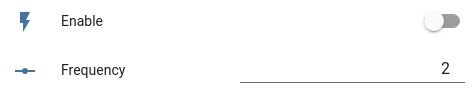
ESPHome can be extended with the help of CustomComponents. A custom component has a setup and a loop function which are called regular by ESPHome. We use a custom component to run our blink code. To control the enable and frequency variables, we create a template number and a template switch entry in our YAML. This will create two entities in Home Assistant where we can set the values.

number:
  - platform: template
    name: "Frequency"
    id: blink_frequency
    optimistic: true
    min_value: 0.1
    max_value: 100
    step: 0.1
    restore_value: true

switch:
  - platform: template
    name: "Enable"
    id: blink_enable
    optimistic: true
    restore_state: true

When we create a CustomComponent we need to create a code file and register the Component in the config YAML. During the registration we can pass references to the switch and number inputs:

esphome:
    [...]
    includes:
    - advancedBlinkComponent.h

custom_component:
- lambda: |-
    auto myComponent = new AdvancedBlinkComponent(id(blink_enable), id(blink_frequency));
    return {myComponent};

The next step is to create the file advancedBlinkComponent.h next to the YAML file with the following content:

#include "esphome.h"

#define LED_PIN 2

class AdvancedBlinkComponent : public Component
{
public:
  unsigned long last_led_change;
  bool enable = false;
  float frequency = 1;

  AdvancedBlinkComponent(esphome::template_::TemplateSwitch *&_enable, esphome::template_::TemplateNumber *&_frequency)
  {
    _enable->add_on_state_callback([this](bool newState)
                                   { enable = newState; });
    _frequency->add_on_state_callback([this](float newFrequency)
                                      { frequency = newFrequency; });
  }

  void setup() override
  {
    pinMode(LED_PIN, OUTPUT);
    last_led_change = millis();
  }

  void loop() override
  {
    if (enable == false)
    {
      return;
    }

    unsigned long now = millis();

    if (last_led_change + 1000 / frequency  < now)
    {
      digitalWrite(LED_PIN, !digitalRead(LED_PIN));
      last_led_change = now;
    }
  }
};

We use the add_on_state_callback function on the passed inputs to set our variables whenever a new value is received by ESPHome. The rest of the code is unchanged but wrapped in a new class which extends the ESPHome Component class. The complete ESPHome project is in the folder esphome

When everything is compiled and uploaded, you can now add the device to Home Assistant and you should see these controls:

A hardware switch for grub

After years of running dual boot systems and always waiting for grub to load and select the desired OS, I finally built a hardware switch to select the OS. You can use the SAVEDEFAULT option in GRUB to remember the last choice and booting from Linux to Windows might work with grub-reboot X. But I was looking for an option which allows me to select the system for the next boot, then turn on my pc and walk away.

Recently I stumbled upon this hackaday post where Stephen used a microcontroller to serve a dynamic file which is read by grub. In the comments Stephen wrote: “You can achieve this pretty simply by switching power to a flash drive and checking for the presence of that volume UUID […]” and that’s what I have done.

WARNING: If you don’t know how to recover from a broken grub, do not mess with the config.

A USB B port soldered to a USB A port with a switch on the VCC.

I added an old 512MB USB stick and a quickly printed case

To the software part:

  • format the stick as fat32
  • get and copy the uuid (sudo blkid it should be something like XXXX-XXXX)
  • modify a file in /etc/grub.d/ to add the following lines to the generated grub file:
search --no-floppy --fs-uuid --set=LinuxUSB XXXX-XXXX

if [ "\${LinuxUSB}" ] ; then
  set default="0"
else
  set default="2"
fi
  • update grub with sudo grub-mkconfig -o /boot/grub/grub.cfg

Grub will now boot entry 0, if the stick is connected, entry 2 otherwise. You don’t need the hardware switch, you can also just plug and unplug the stick.

While writing this post, I also found this project, which looks way more flexible.

Use android phone as USB webcam for OBS

There are two common known programs to use your android phone as a webcam. The first one is DroidCam, the other one is IP Webcam. DroidCam offers the option to use it over USB, but is limited in the supported options. IP Webcam does only support connections over IP (which equals to WiFi for most smartphones).

The problem with WiFi might be a laggy video feed, when the connection is not very good.

So wouldn’t it be nice to use IP Webcam over a USB connection? The idea is to use adb.exe to forward the port of IP Webcam (normally 8080) to your computer.

HowTo

Okay, so here is a step by step guide:

  1. Enable Developer Mode on your phone and enabled USB debugging. There are a lot of tutorials to do this. For example, follow this one.
  2. Get adb.exe. To get it, you can download the SDK platform tools for windows from here. From that zip you only need adb.exe, AdbWinApi.dll and AdbWinUsbApi.dll. Copy the files in a new directory.
  3. In IP Webcam just scroll down and click on start server. In the new screen you will see a port number right after your IP-Address (like 192.168.178.24:8080).
  4. Open a terminal in the new directory by holding Shift and right click and click on “Open PowerShell Here”.
  5. Type the following command .\adb.exe forward tcp:8081 tcp:8080 to forward the port 8080 from the phone to your computer to port 8081.
  6. In OBS add a browser source and set the following URL: http://localhost:8081/videofeed.

Multiple Webcams

You need multiple webcams and have multiple phones? Follow the steps from above, but when you forward the port, you need to specify the device. You can get all devices to your computer with the command adb.exe devices -l. Now copy the device identifier (something like BH4023468D) and use it in the forwarding command like this: .\adb.exe -s BH4023468D forward tcp:8081 tcp:8080. For the next phone, replace 8081 with 8082, 8083, … and use the new port in another browser source in OBS.

MQTT Dashboard

If you ever develop something with mqtt, you might need a client to send some test messages and view the published messages. To generate a simple dashboard with buttons and subscribers to different topics, a friend of mine and I created a webapp.

The Code can be found on github at https://github.com/DirkHeinke/mqttDashboard and a running demo is here: http://mqttdashboard.dirkheinke.de/

Jekyll, Travis, Docker - permissions denied

After trying to redeploy my blog with travis, the build failed with this message:

[...]
jekyll 3.8.3 | Error:  Permission denied @ dir_s_mkdir - /srv/jekyll/_site

The problem was, that travis set permissions for uid 2000, but the container runs with uid 1000. Adding write permissions to the folder allows jekyll to create a new folder and write the output. My docker run command now looks like this:

docker run --rm --volume=$(pwd):/srv/jekyll jekyll/jekyll /bin/bash -c "chmod a+wx . && jekyll build -V"